By John Trout
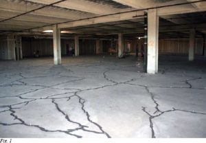
The mother of all delaminations! was the apt characterization of one observer upon visiting the 128,000 ft2 (11,682 m2) overlay (refer to Fig. 1). At least 50% of the area had lost bond. In addition, there were miles of cracks and many construction joints had separated—over 17,000 linear feet (5182 m) combined.
 Had time and accessibility allowed, wisdom may have dictated reducing the overlay to rubble, scooping it up, and starting over. But the floor was in the upper reaches of a high-rise and was needed within 2 months. Epoxy injection was deemed the only feasible repair.
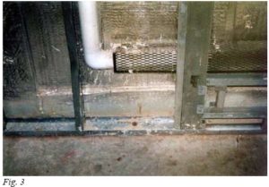
There were issues to be resolved before work could commence. One was the possibility that injected resin might drain from the delaminations through any open cracks or joints in the structural slab. Full support of the overlay could then be lost, and damage to furnishings could occur if the floor below was in use (refer to Fig. 2 and 3). Although no cracks were found in the structural slabs, joints at exterior walls and penetrations remained a concern because interior wall insulation, finishes, beams, and other obstructions prevented access.

The concern was justified, as leaks did occur. But, being aware of the problem, repair crews were able to minimize seepage by reducing injection pressures and closely monitoring resin consumption in the vicinity of the joints.
 Another concern was the need to pin the overlay segments to prevent lifting during injection. Steel pins are often installed in a grid pattern to secure typical 2 in. (5 cm) overlays, but here, cores revealed a minimum overlay thickness of 3 in. (7.6 cm). Considering the slab thickness and narrow crack width (few greater than 0.020 in. [0.51 mm]), the evaluation concluded that interlocking of aggregate and binding between the segments would frustrate lifting at prudent injection pressures.
Some questions remained, however, as to whether the installation of steel pins as additional reinforcement was wise. But again, this was deemed unnecessary, considering that the strength of the overlay concrete was good, the floors would remain at a constant temperature, the overlay had been in place for over 2 years, heavy loads were to be static, traffic would be light, and, of course, confidence that the repair would render the slab segments monolithic and stable.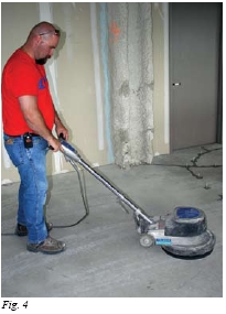
The repair included the injection of all cracks and construction joints greater than 0.005 in. (0.13 mm) in width. Because cracks were reflected from virtually all of the delaminations, no holes were drilled to inject isolated voids. Three proportioning dispensers were used: two for resin injection and another to serve as a hydrant for the epoxy gel to be used as a seal over the cracks prior to injection.
At the beginning of the repair, a short crew of three was brought in for a few days. This provided an opportunity to determine the most advantageous techniques and organization to assure quality work and avoid confusion amidst the sizable crew that would be needed. Plans were laid, and within a few days the workforce was expanded around the core cadre.
It was quickly realized that a sweep of the entire floor with a 16 in. (40 cm) floor sander followed by a vacuum was more productive than tracing each crack with a hand wire brush or power tool (refer to Fig. 4). The cracks were air blasted to remove any impacted fines shortly before application of the epoxy crack sealer.
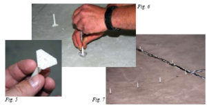
A special setting tool was helpful in positioning the surface mounted porting adapters along the cracks and joints. The sealer used to sec
ure the adapters was the same as that used to seal the cracks (refer to Fig. 5, 6, and 7). The adapters were spaced on nominal 12 in. (30 cm) centers.
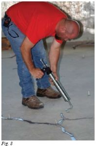
Caulking guns were used to deposit the sealer along the cracks. The seal was then tooled as necessary (refer to Fig. 8).
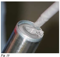
The hydrant concept was invaluable, providing thoroughly mixed and precisely proportioned material “on tap” throughout the project (refer to Fig. 9 and 10). There was no need for manual proportioning, mixing, and filling of caulking guns. There was also virtually no clean-up because the mixers were disposable. The labor saved was substantial.
Prompt mixing and issue of the sealer also improved bond to the concrete because workers were able to place it fresh, before it began to stiffen. This was important because the bond of an epoxy, like any other adhesive, depends in large part upon wetting action to penetrate into a surface. When an epoxy is prepared manually, much of the working life of the product is often sacrificed in the preparation, making it difficult to place the product before it has stiffened.
The resin selected for the sealer was free of significant abrasives that could jam or damage the piston displacement hydrant dispenser, and of a viscosity that quickly wet into the surface. The success of a project is often in large part attributable to sensible resin selections. 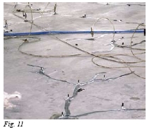
The injection of numerous (usually nine) ports simultaneously from a single dispenser was a technique that played a major roll in production (refer to Fig. 11). Two workers orchestrated the connections among a welter of porting adapters. The routine called for the port connectors to be managed as a battery; that is, all of the connections were closed, disconnected, relocated, and the valves reopened together. The dispenser kept the resin “on-tap” at a constant and uniform pressure throughout the operation.
Port connections were kept in place until the dispenser was nearly stalled, indicating that local voids were probably filled. Additional injection under the circumstance would only urge resin into remote locations likely to be filled more quickly with the next move. Bleed from remote ports occurred often and was always encouraging, but rarely signaled a sensible move. A reluctance or refusal to accept additional resin is a more reliable indicator of local saturation of a fault.
Following removal of the port connectors, caps were placed over the adapters. This prevented resin from drooling from the adapter as pressure was introduced at adjacent ports.
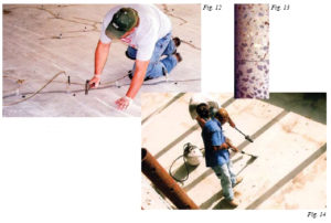
Quality control was ongoing. Filling of delamination voids was confirmed not only by an increasing resistance to penetration as large local voids were filled, but also by tapping of the surface with a hammer (refer to Fig. 12 and 13). The penetration of the resin into the delaminations was closely monitored as the hollow report (so pronounced beforehand) was muted. Cores confirmed the value of this practice.
No lifting of slab segments was detected. If a segment were to be disturbed, cracks would have quickly and surely reflected through the rigid epoxy seal over the cracks and joints. No such cracking occurred.
Following cure of the injected resin (refer to Fig. 14), 200,000 Btu torches were used to soften the sealer so that it could be easily and cleanly shaven from the surface.
Brief ratio assurance checks of the equipment were made weekly on site. At no time did the equipment fail to precisely proportion and thoroughly mix the injection resin. The three dispensers flawlessly dispensed over 2000 gal. (7571 L) of injection resin and 150 gal. (568 L) of the epoxy gel sealer.
The final crew of eight workers completed the project well within the required 2 months. The right equipment and the right product for the job can make all the difference in a successful completion.
For a copy of this document in printable PDF format, please download
Repairing Large Delaminated Overlays with Epoxy Injection